
Cloud Design Patterns in Action: Real-World Use Cases for Microservices-Part 1
Cloud Design Patterns in Action: Real-World Use Cases for Microservices-Part 1
“A good architecture will allow a system to be born as a monolith, deployed in a single file, but then to grow into a set of independently deployable units, and then all the way to independent services and/or micro-services.”
Robert C. Martin (Clean Architecture)

Table Of Content
- Preface
- When Modular Monolithic Architecture ? What is Best practices ?
- Cloud Design Patterns
- Ambassador pattern
- Anti-corruption Layer pattern
- Asynchronous Request-Reply pattern
- Backends for Frontends pattern
- Bulkhead pattern
- Cache-Aside pattern
- Choreography pattern
- Circuit Breaker pattern
- Claim-Check pattern
- Compensating Transaction pattern
- Competing Consumers pattern
- Compute Resource Consolidation pattern
- Making a conclusion
Preface
Before we dive into the realm of cloud-native design patterns and microservice design, let us understand where we are coming from — and why in the world we ever had to conform.
For decades, monolithic architectures were the go-to way of building software. They offered a simple way of structuring applications: everything in one codebase, deployed as one thing. Early in a product’s life, it was sensible. It allowed teams to move fast, make deployment simple, and reduce overhead.
As applications became larger and more complex, the shortcomings of monolithic systems became evident:
Scaling meant copying the entire application, even when only one piece needed more resources.
Deployment cycles were slower because making a change to one module involved deploying and testing the entire system.
Maintainability was worse because tightly coupled pieces meant a higher barrier to altering or replacing pieces of the system without ruining other pieces.
Team productivity was limited because several developers or teams sharing the same codebase would end up getting in each other’s way.
To address such issues, the world of business shifted towards microservice architecture. Microservices instead create one large application and, instead, break it up into pieces and smaller, independent services based on individual tasks they perform. The modularity increases, scaling, and perhaps above all — cleanable, easier-to-develop-in-time codebases.
This document explores how to design these systems effectively using cloud-native patterns, and how to apply them to real-world scenarios. Whether you’re modernizing a legacy monolith or starting fresh with microservices, understanding these patterns is key to building reliable, scalable, and maintainable cloud applications.
In software business complexity may grow rapidly and destroy your life. That is why when an application begins development every expectation must be considered probably well-designed monolithic application is perhaps the best fit for your architecture. Once we have implemented Microservices-based solution, if we cant manage the boundaries our domain will become overly complex, and over-engineering may happen to our domains. We shall take our project towards a much more maintainable and manageable version.
When Modular Monolithic Architecture ? What is Best practices ?
If you are starting a new project and do not have an idea of which software architecture to follow, you can start with a modular monolithic architecture. With a thin line of demarcation in this chapter, you can convert your current system to a microservice-based system. In this case, the monolithic application that you have already developed should be with some standards. Of course, this is not a rule mentioned somewhere, it is simply based on my experiences.
What is Modular Monolithic Architecture?
Modular
Monolithic Architecture is a software architecture that combines the benefits of modular design with the
simplicity of monolithic architecture. It involves dividing the system into a set of loosely-coupled
modules, each with a well-defined boundary and explicit dependencies on other modules.
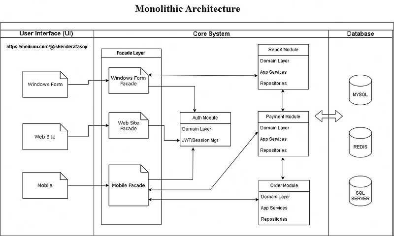
The monolithic modular architecture isolated our application logic into modules and each module will be isolated and independent. Then, there must be a business logic for each module — and, if necessary, its database or schema.
User Interface(UI) layer only communicate Core system with Façade Services Or Api Gateways. Façade Services/Api Gateway is only way to communicate submodules. Each submodule access their own schema. In a entire of time this module can separate the core system easily.
Sample directory view
/MyCompany.MyApp
│
├── MyCompany.MyApp.API
│   ├── Controllers
│   │   ├── AuthController.cs
│   │   ├── OrderController.cs
│   │   └── PaymentController.cs
│   └── Program.cs / Startup.cs
│
├── MyCompany.MyApp.Auth
│   ├── Application
│   │   ├── Commands (Login, Register)
│   │   ├── Handlers
│   │   ├── Services (e.g., IAuthService)
│   │   └── DTOs
│   ├── Domain
│   │   ├── Entities (User, Role)
│   │   ├── ValueObjects (Email, PasswordHash)
│   │   └── Interfaces (IUserRepository, ITokenService)
│   ├── Infrastructure
│   │   ├── Persistence (EFCore DbContext)
│   │   ├── Repositories (UserRepository)
│   │   └── Services (JwtTokenService)
│   └── AuthModule.cs (extension method for DI config)
│
├── MyCompany.MyApp.Order
│   ├── Application
│   │   ├── Commands (CreateOrder, CancelOrder)
│   │   ├── Queries (GetOrderById)
│   │   └── DTOs
│   ├── Domain
│   │   ├── Entities (Order, OrderItem)
│   │   └── Interfaces (IOrderRepository)
│   ├── Infrastructure
│   │   ├── Persistence (OrderDbContext)
│   │   └── Repositories (OrderRepository)
│   └── OrderModule.cs
│
├── MyCompany.MyApp.Payment
│   ├── Application
│   │   ├── Commands (ProcessPayment)
│   │   └── DTOs
│   ├── Domain
│   │   ├── Entities (PaymentTransaction)
│   │   └── Interfaces (IPaymentService)
│   ├── Infrastructure
│   │   ├── Repositories
│   │   └── ExternalServices (StripeAdapter, PayPalAdapter)
│   └── PaymentModule.cs
│
├── MyCompany.MyApp.Shared
│   ├── Common (Extensions, Utilities)
│   ├── Exceptions
│   ├── Logging
│   └── Security (PasswordHasher, JwtOptions)
│
├── MyCompany.MyApp.Tests
│   ├── Auth.Tests
│   ├── Order.Tests
│   ├── Payment.Tests
│   └── Integration.Tests
│
└── MyCompany.MyApp.sln
And as a solution we have decided to learn Modular Monolithic Architecture with the Dependency Rule principle. The idea is provide more isolation and add new features in encapsulated modules in our current architecture.
Architecture Design Journey
The evolution of software architecture is not just about technology shifts — it’s about adapting to complexity, scale, and speed. Here’s a high-level view of the architectural journey modern systems often take:
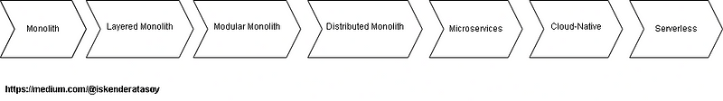
- Monolith, Everything in one place
- Layered Monolith, Separated concerns by technical layers
- Modular Monolith, Domain-driven modules, single deployment
- Distributed Monolith, Bad microservice attempt, tight coupling remains
- Microservices, Independent services & DBs
- Cloud-Native, Optimized for cloud environments
- Serverless, Fully managed, event-driven functions
Cloud Design Patterns
Designers develop workloads by combining platform services, functionality, and code to fulfill functional and nonfunctional requirements. In order to efficiently design workloads, you must be aware of these requirements and select topologies and approaches that address the issues in your workload’s constraints. Cloud design patterns have solutions for most of the challenges.
System design is heavily grounded in established design patterns. You can build infrastructure, code, and distributed systems with a combination of these patterns. These patterns play a critical role in the development of trusted, highly secure, cost-optimal, operationally efficient, and high-performing cloud applications.
The below cloud design patterns are technology-agnostic, which means that they can be used in any distributed system. These patterns can be implemented in Azure, other cloud platforms, on-premises environments, and also in hybrid setups.
Cloud workloads are also prone to the fallacies of distributed systems, which are common but erroneous assumptions about the way distributed systems work. A few of these fallacies include:
- The network is secure, Assumes built-in security; ignores the need for encryption, auth, and zero-trust.
- The network is reliable , Assumes stable connectivity; ignores timeouts, dropped packets, and retries.
- Latency is zero, Assumes instant communication; overlooks the impact of network delay and distance.
- Bandwidth is infinite, Assumes unlimited transfer capacity; ignores limits, cost, and bottlenecks.
- Topology doesn’t change, Assumes a static system; ignores auto scaling, failover, and ephemeral nodes.
- There’s one administrator, Assumes centralized control; ignores cross-team ownership and access boundaries.
- Component versioning is simple , Assumes services can upgrade freely; ignores compatibility, dependencies, and contract management.
- Observability can be delayed , Assumes you can “add logs later”; ignores the critical need for early insights and failure tracing.
These misconceptions can cause faulty workload designs. The design patterns do not get rid of these misconceptions but help in raising awareness, provide compensation strategies, and provide mitigations. There are trade-offs with each cloud design pattern. Prioritize why you must employ a certain pattern instead of how you should employ it.
Consider how to use these industry-standard design patterns as the building blocks of a well-architected workload design. Each design pattern is represented by one or more pillars of the Any Well-Architected Cloud platform. There are some patterns that introduce trade-offs that affect the goals of other pillars.
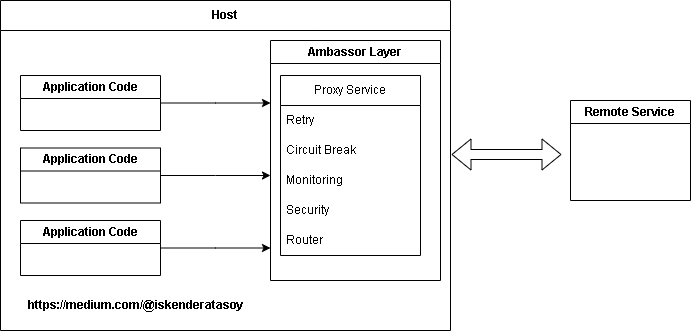
Ambassador pattern
Create assistant services that make network requests via a consumer service or app. An ambassador service can be treated as an out-of-process proxy collocated with the client.
This is a convenient pattern to offload common client connectivity work such as monitoring, logging, routing, security (for example, TLS), and resiliency patterns in an agnostic manner regarding the language. It is typically used for legacy applications, or other applications that cannot be easily modified, such as to include their networking features. It also allows a specialist team to bring in those features.
Context and problem
Cloud applications will require
features such as circuit breaking, routing, metering and monitoring, and the ability to change
configuration pertaining to the network. It might be difficult or even impossible to apply updates to
existing apps or older code libraries to include these features, as the code is not supported or cannot be
easily changed by the development team.
Network calls can also have substantial configuration for connection, authentication, and authorization. If these calls are shared across various applications, built on various languages and frameworks, the calls have to be configured for each of those. Additionally, network and security features may have to be managed by a centralized group within your organization. With an enormous code base, such a group becomes perilous to change application code with which they might not be familiar.
Solution
Put client libraries and frameworks into an
external process that acts as a proxy between your application and external services. Host the proxy on
the same host environment as your application to allow control over routing, resiliency, security
features, and to avoid any host-related access limitations. You can also use the ambassador pattern to
standardize and extend instrumentation. The proxy is able to monitor performance metrics such as latency
or utilization, and this monitoring takes place within the same host environment as the application.
Samples
An Ambassador Pattern example. Contribute to joaosczip/k8s-ambassador development by creating an account on GitHub.github.com
A simple sample applying ambassador pattern for microservices - nestjslatam/ambassador-pattern-microservicegithub.com
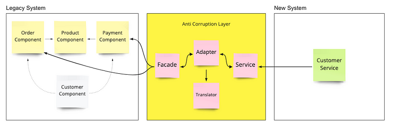
Anti-corruption Layer pattern
Use a façade or adapter layer between different subsystems that do not have the same semantics. The layer translates requests that one subsystem makes to the other subsystem. Use this pattern to keep an application’s design from being dictated by its dependencies on subsystems outside the application. This pattern was first described by Eric Evans in Domain-Driven Design.
Context and problem
Most applications rely on other systems for some data or functionality. For example, when an application is being migrated to a new system, it may still need accessible legacy resources. New functionality must be able to invoke the legacy system. This is especially true for incremental migrations, where features of a large application are migrated to a new system over time.
Such legacy systems tend to possess quality issues such as convoluted data schemas or antiquated APIs. The features and technology used by legacy systems can be significantly disparate compared to other more modern systems. To achieve interoperability with the legacy system, the new application may need to introduce aged infrastructure, protocols, data models, APIs, or other features that you would not otherwise put in a modern application.
Leaving the interface between old and new systems open may force the new system to adhere to at least some of the legacy system’s APIs or other semantics. If those legacy features are badly designed, their continued maintenance “corrupts” what would otherwise be a well-designed modern application.
The same issues may occur with any external system that is not under the control of your development team, not just legacy systems.
Solution
Isolate the different subsystems by placing an anti-corruption layer between them. This layer translates communications between the two systems, allowing one system to remain unchanged while the other can avoid compromising its design and technological approach.
Samples
https://docs.aws.amazon.com/prescriptive-guidance/latest/cloud-design-patterns/acl.html
Asynchronous Request-Reply pattern
The Asynchronous Request-Reply is a communication messaging pattern that finds extensive use in distributed systems as well as in microservices architecture. It provides a sender an opportunity to post a request and continue its processing without waiting for an immediate reply. The response, when available, is passed back to the requester through a separate channel or callback.
Context and issue
It is not rare in modern application
development that client applications — often code running within a web-client (browser) — depend on remote
APIs to provide business logic and accumulate functionality. These APIs can be explicitly
application-specific or common services provided by a third party. Normally, such calls over the API are
made over the HTTP(S) protocol with REST semantics.
On average, APIs to a client application are
designed to be of the order of 100 ms or even less. There are various factors that may have an impact on
response latency, including:
A hosting stack of the application. Security factors. Relative geographic location of the caller and the backend.
- Network infrastructure.
- Load at the time.
- Size of request payload.
- Processing queue.
- Backend request process time.
Each of these can add latency to the response. Some can be mitigated by scaling out the backend. Others, such as network infrastructure, are beyond the application developer’s control. All but a handful of APIs can respond in time for responses to return on the same connection. Application code can make a synchronous API call in a non-blocking fashion to give the illusion of asynchronous processing, which is the best way to do it for I/O-bound operations.
In some cases, however, backend work can be long-running, of the order of seconds, or can be a background task taking minutes or even hours. Then it is not feasible to wait for the work to complete before returning the response to the request. This is an issue for any synchronous request-reply mechanism.
Some architectures meet this challenge by the addition of a message broker to divide the request and response stages. This division is typically achieved through implementation of the Queue-Based Load Leveling pattern. This division can make the client process and the back-end API independent in terms of scaling. But this division also adds additional complexity when success notification is required for the client, as this step needs to be made asynchronous.
The majority of the same concerns discussed for client applications also apply to server-to-server REST API calls within distributed systems — for example, a microservices architecture.
Solution
One of the solutions to this problem is to do HTTP polling. Polling is beneficial to client-side code because it is hard to provide call-back endpoints or do long running connections. Even if callbacks can work, the extra libraries and services required can sometimes introduce too much extra complexity.
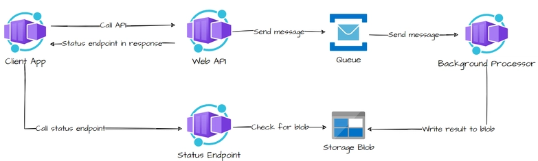
Samples
- A web client sends a request to generate a report.
- The backend accepts the request, sends it to a worker via a message broker (like RabbitMQ), and immediately responds with “Report request received.”
- The worker generates the report asynchronously.
- Once done, the worker sends the result back via another queue or API callback.
- The client is notified (via webhook, polling, or push) when the report is ready.
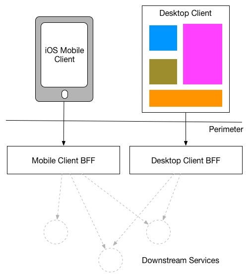
Backends for Frontends pattern
Backends for Frontends (BFF) is an
architectural pattern where each type of frontend (i.e., web, mobile, smartwatch) will be serviced by a
separate backend service.
Instead of the single, generic API for every client, the BFF acts as a
mid-layer between frontend and backend core services and customizes responses to the specific frontend it
serves.
Context and issue
Consider an application that was developed with a desktop web interface and an accompanying backend service. As business requirements changed over time, a mobile interface was added. Both interfaces communicate with the same backend service but the capacity of a mobile device is very different from a desktop browser, with regards to screen real estate, processing capability, and rendering limitations.
The backend service would get competing demands from different frontends, and it would be subject to a high degree of changes and end up being a bottleneck for development. Competing updates and ensuring compatibility result in too much effort on a single deployable asset.
With the backend service being owned by another team, it can create a gap between backend and frontend teams, which causes delays in reaching an agreement and balancing demands. For example, change requests by one frontend team must be validated with other frontend teams before integrating.
Solution
Add a new layer that handles only the interface-specific requirements. This layer, called the backend-for-frontend (BFF) service, is inserted between the frontend client and the backend service. If the application supports more than one interface, create a BFF service for each interface. For example, if you have a web interface and a mobile app, you would create separate BFF services for each.
Samples
The most flexible and standards-compliant OpenID Connect and OAuth 2.x framework for ASP.NET Core …github.com
Bulkhead pattern
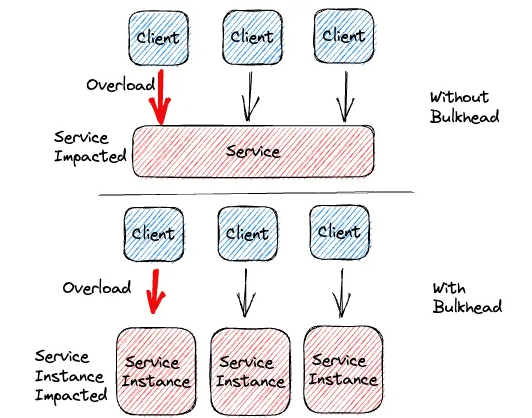
Bulkhead design is a failure-tolerant application pattern. In bulkhead design, also known as cell-based design, parts of an application are divided into pools so that when one fails, the others can still work. It is so named because it is similar to the partitioned spaces (bulkheads) of a ship hull. When a boat’s hull is breached, only the compromised portion fills with water, and this does not make the boat sink.
Context and issue
A cloud application may have a number of services, and each service can have one or more consumers. Overload or failure in the service will impact all consumers of the service.
Moreover, a consumer may send requests to multiple services simultaneously, utilizing resources per request. When the consumer initiates a request to an unresponsive or misconfigured service, resources used by the client’s request may not be released in a timely manner. As the client continues to send requests to the service, the resources are drained. For example, the client connection pool is drained. Consumer requests to other services at this point are affected. Eventually, the consumer is unable to make requests to other services, not only the initial unresponsive one.
The same problem of resource overload occurs in services with multiple consumers. Too many requests coming from a single client can drain available resources within a service. Other consumers are no longer able to use the service, with the effect of a cascading failure.
Solution
Partition service instances into different groups, based on consumer load and availability requirements. This design helps to isolate failures, and allows you to sustain service functionality for some consumers, even during a failure.
Samples
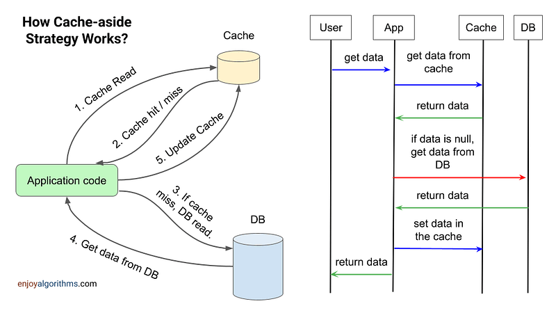
Cache-Aside pattern
Pre-load data on demand into a cache from a data store. This can improve performance and also helps to maintain consistency between data in the cache and data in the underlying data store.
Context and issue
Applications use a cache to support efficient repeated access to data held in a data store. It is unrealistic, however, to expect cached data always to be perfectly consistent with data in the data store. Applications need to have some mechanism in place to ensure that the cache data is as up to date as possible, but also is capable of recognizing and handling situations where data in the cache is out of date.
Solution
All commercial caching mechanisms provide support for read-through and write-through/write-behind operations. In these mechanisms, an application reads data by referencing the cache. If the data is not resident within the cache, it’s read out of the data store and cached. Any modifications of data resident in the cache automatically write back into the data store as well.
For caches that do not support this feature, it is up to the applications that utilize the cache to keep the data up to date.
An application can simulate the read-through caching feature by using the cache-aside pattern. The cache-aside pattern loads data into the cache as needed. The figure shows implementing the Cache-Aside pattern to cache data.
Samples
You can design this pattern with any NoSQL engine for example : Redis , Memcached, MongoDB , Cassandra, Amazon DynamoDB (with DAX), Couchbase , HBase
Choreography Pattern
The Choreography Pattern is a distributed style
of microservice coordination.
Rather than a single orchestrator dictating the flow (such as in the
Orchestration pattern), every service responds to events and sends new events in return.
Imagine it as a dance — every service is aware of its role and acts according to cues (events), not instructions.
Context and issue
A cloud application is usually split into many fine-grained services that collaborate to handle an end-to-end business transaction. Even one operation (within a transaction) can lead to multiple point-to-point invocations between all services. Ideally, the services must be loosely coupled. It’s hard to model a workflow that’s distributed, efficient, and scalable since it tends to involve complicated interservice communication.
One common pattern of communication is to use a centralized service or an orchestrator. Requests go through the orchestrator since it delegates duties to the responsible services. Individual services just complete their task and are not knowledgeable about the full workflow.
The orchestrator pattern is typically custom software and includes domain knowledge about the work of the services. One benefit is that the orchestrator can accumulate the status of a transaction based on the result of each operation done by the downstream services.
Solution
Separate the transaction logic across services,
and allow each service to decide how and when to commit to a business process.
Instead of relying on a
centralized component to direct the workflow, this pattern reduces the dependence on custom orchestration
logic. Every service contains duplicated business logic and coordinates with others by utilizing
events — choreographing the workflow without any point-to-point communication that is direct.
Samples
You can explore related patterns such as
Saga, Two-Phase Commit (2PC), Three-Phase Commit (3PC), or the Outbox Pattern to manage distributed transactions and
ensure data consistency.
For event-driven communication, you can use tools like Apache Kafka, RabbitMQ, or Amazon SNS/SQS to enable services to publish and
subscribe to events seamlessly.
Circuit Breaker pattern
The Circuit Breaker pattern helps deal with faults that could take various amounts of time to recover from if an application attempts to communicate with a remote resource or service. A circuit breaker temporarily avoids allowing access to a failing service as soon as it detects failures. This is accomplished to prevent recurring failed attempts in order for the system to actually recover. The pattern can be used to increase the resiliency and stability of an application.
Context and issue
In a distributed environment, requests to remote resources and services can fail because of transient faults. Transient faults include overcommitted or temporarily unavailable resources, sluggish network connections, or time-outs. Such faults typically self-heal in a matter of milliseconds. To help sustain these faults, you need to architect a cloud application to use a technique, like the Retry pattern.
Unanticipated events can induce faults that can take longer to correct. Such faults can range in severity from a level of a partial loss of connectivity to complete service failure. In these situations, an application ought not to continually retry an operation with a low likelihood of success. Instead, the application must quickly recognize the failed operation and handle the failure accordingly.
If a service is in use, an error in one part of the system may result in cascading errors. For example, you can establish an operation that invokes a service to employ a time-out. If the service fails to respond within this period, the operation returns a failure message.
But this method can serialize concurrent requests to the same operation until the time-out period has elapsed. Such blocked requests can hold valuable system resources, such as memory, threads, and database connections. This problem can consume resources, which might make other unrelated parts of the system fail that need to use the same resources.
In such situations, an operation has to fail right away and attempt to call the service only if it has a high chance of being successful. To resolve this problem, make the time-out shorter. However, ensure that the time-out is long enough so that the operation succeeds most of the time.
Solution
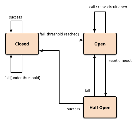
When a component or service is failing, repeated attempts to communicate with it would put the system under additional stress and lead to cascading failures. This pattern avoids making repeated calls to a failing service, thus protecting the system and allowing it to recover.3 state exist given pattern :
- Closed State: The circuit is closed, and requests can go through normally.
- Open State: After a certain number of failures is reached, the circuit is opened and requests are prevented from going through to the failing service.
- Half-Open State: Finally, the circuit enters half-open state in which small amounts of requests are allowed through to see if the service has come back.
This trend assists systems to stay responsive by separating malfunctioning components and giving them time to recover without drowning them with traffic.
Samples
This repository contains .NET Documentation. Contribute to dotnet/docs development by creating an account on GitHub.github.com
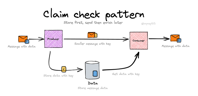
Claim-Check pattern
Claim-Check pattern allows payloads to be carried through workloads without keeping the payload in a messaging system. The pattern inserts the payload into an external data store and uses a “claim check” to retrieve the payload. The claim check is some kind of special, opaque key or token. Applications need to return the claim-check token to the external data store in exchange for the payload.
Context and issue
Claim-Check pattern is a design pattern that optimizes the efficiency of messaging systems by avoiding direct sending of big payloads. Instead of sending big messages through the messaging system, the payload is stored on an external data repository, and a tiny claim-check token is sent. The receiving application can use this token to request the payload from the repository. Step works :
- Payload Storage: The payload is stored in an external storage.
- Claim-Check Token Generation: A claim-check token is generated uniquely and associated with the payload.
- Send the Token: The messaging system sends a message containing the claim-check token, instead of the actual payload, to the target application.
- Retrieve Payload: The receiving application copies the claim-check token from the message, retrieves the payload from the external data store using the token, and processes the payload.
This design pattern is handy for reducing load on messaging systems and improving performance by sending light-weight tokens only instead of bulky payloads.
Solution
Use the Claim-Check pattern to relay large or sensitive message payloads to an external data store and replace them in the messaging system with a light-weight claim-check token. The token allows the target application to retrieve and process the payload independently.
This pattern works best when:
- Message size exceeds messaging system capacity.
- Large payloads degrade messaging throughput or performance.
- You need to protect sensitive data from exposure while in transit.
You want to make routing simpler by avoiding costly processing (e.g., serialization/encryption) within middleman services.
Decoupling the message payload from the message, the Claim-Check pattern increases scalability, security, and system effectiveness.
Sample
Sample implementations for cloud design patterns found in the Azure Architecture Center. …github.com
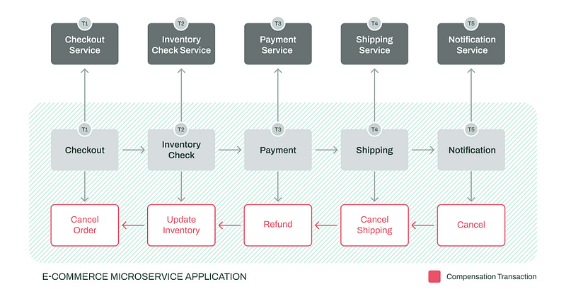
Compensating Transaction pattern
The Compensating Transaction pattern comes in useful where you are handling eventually consistent operations which are multi-step in nature. When one of the steps fails, this pattern allows you to reverse or roll back the failed steps’ changes. This is mostly common in cloud-based applications that handle complex business flows where there cannot be a full transactional support.
Context and issue
Cloud applications often operate on distributed data that resides in different locations. To improve scalability and performance, they typically defy strong consistency and opt for eventual consistency, where operations are divided into individual steps that put the system in a temporarily inconsistent condition until their completion.
One of the biggest challenges of this model is handling failure at runtime. Since you can’t always just roll back — because the other processes have updated things or because there’s intricate business logic — you need to have compensating actions to roll back safely through all the systems involved, be it databases or external services.
Solution
A compensating transaction is used to undo the impact of an aborted operation in an eventually consistent system. Rather than merely reverting to the initial state — perhaps in conflict with concurrent updates — it applies smart, application-dependent reversal operations upon taken actual steps.
Normally, a workflow engine traverses each step and the corresponding undo logic. When an operation is failed, the workflow backtracks through successfully completed steps, taking compensating actions. These undo steps need not necessarily be called in strictly reversed order and may be called concurrently wherever feasible.
As compensating transactions are eventually consistent themselves, they too may fail. Thus:
Undo steps need to be idempotent (safe to repeat).
The system should recover from failure.
In some cases, manual handling may be required, and the system must provide full context of error.
This solution has a direct correlation with the Saga pattern used in distributed systems.
Sample
A four implementations of the Compensating Transaction pattern in Temporal in go, python, java and typescript …github.com
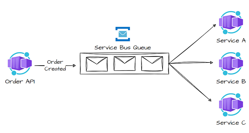
Competing Consumers pattern
Allow multiple consumers to process messages from one messaging channel concurrently. This enables the system to process messages in parallel, improving throughput, scalability, and availability, and helping distribute loads effectively.
Context and issue
A cloud application often faces a massive volume of incoming requests. Instead of processing each request sequentially, a common approach is to route them through a messaging system to an asynchronous consumer service, which handles the requests in parallel. This prevents the application’s business logic from being blocked while waiting for requests to be processed.
The volume of requests can vary greatly over time due to factors like spikes in user activity or accumulated requests from multiple tenants, resulting in unpredictable load patterns. During peak periods, the system may need to handle hundreds of requests per second, whereas, at other times, the volume could be minimal. Additionally, the nature of the tasks involved in processing these requests can change dynamically.
If only a single instance of the consumer service is used, it may become overwhelmed by the volume of requests. Similarly, the messaging system could be flooded with an overwhelming number of messages. To manage this fluctuating workload, multiple instances of the consumer service can be deployed. However, these consumers must be synchronized to ensure that each message is processed by only one consumer, and the load must be evenly distributed to prevent any single instance from becoming a bottleneck.
Solution
Use the communication channel between the application and the instances of the consumer service through a message queue. The application places requests as messages in the queue, and the consumer service instances consume and handle the messages. This architecture allows the same set of consumer service instances to handle messages from any other instance of the application. The following diagram shows how a message queue can be used to distribute workloads among multiple instances of a service.
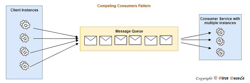
Sample
The Competing Consumers pattern makes it
possible for a distributed system to process huge numbers of messages in an efficient manner by
facilitating multiple instances of consumers to consume from a common shared queue. RabbitMQ, Apache
Kafka, Amazon SQS, and Azure Service Bus are some of the well-known utilities used to implement this
pattern, providing scalability, fault tolerance, and load balancing in modern cloud-based systems.
Compute Resource Consolidation pattern
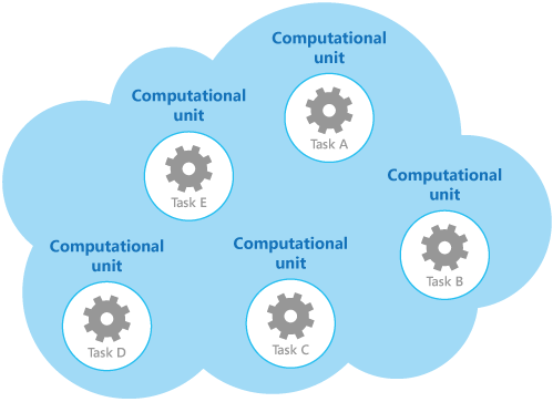
The Compute Resource Consolidation Pattern is concerned with optimizing the use of resources through the consolidation of multiple workloads, applications, or systems onto fewer computing resources with greater power, i.e., servers or cloud instances. It is a highly useful pattern to gain improved efficiency, reduce management complexity, and lower operational costs.
Context and issue
The Compute Resource Consolidation Pattern has the goal to optimize the utilization of computing resources by consolidating workloads to smaller, high-performance units of infrastructure, for instance, servers or cloud instances. The pattern addresses issues with wasted resources, costly operations, and large administration in large environments, particularly in cloud or virtualized environments. Some Key Facts:
- Resource Optimization: Grouping workloads on to fewer virtual servers or machines ensures that available computing resources (storage, memory, CPU) are utilized better, leading to improved resource usage.
- Cost Effectiveness: Lower physical or virtual servers translate to less infrastructure costs, such as energy consumption, cooling, and maintenance. It also minimizes the need for managing a lot of resources.
- Ease of Management : By reducing the number of machines or instances, system administration becomes simpler, with fewer efforts in monitoring, patching, and provisioning resources.
- Improved Scalability : Consolidation simplifies scaling resources, especially in cloud environments, where compute resources could be dynamically provisioned and scaled based on demand.
- Virtualization & Cloud Integration : Techniques like virtualization (e.g., VMware, Hyper-V) and cloud platforms (AWS, Azure) facilitate easier consolidation of workloads without compromising flexibility or availability.
- Performance Efficiency : Workload can be made more balanced and distributed over less number of resources, preventing the bottlenecks of underutilization and allowing resources to scale cost-effectively to meet changing demand.
- Benefits : Cost Savings: Avoids wasting on unnecessary infrastructure and reduced cost of operations.
- Resource Optimization : Maximizes resources utilization to get added performance and prevent wastage.
- Easier Scaling and Management : Allows scaling out and easier management by reducing the number of physical as well as virtual instances.
- Uses Cloud Environments : A good selection for companies heading to the cloud because consolidation of workload onto fewer instances reduces costs and complexity.
- Data Centers : When physical space and power consumption are concerns in data centers, consolidation of workload onto fewer more efficient servers reduces overhead.
- Virtualized Infrastructures : Beneficial where several virtual machines exist in an environment since consolidation of workload reduces VM count and optimizes resource use.
Making a conclusion
👨👦👦 Leave a comment, I am free for discussion with your any kind technical question.
#Microservices #CloudDesignPatterns #CQRS #EventSourcing #APIArchitecture #DistributedSystems #SoftwareArchitecture #CloudComputing #TechPatterns #DevOps